دليل عملي لاستخدام محول STEP STL
اتقن عملية تحويل STL خطوة بخطوة. تعلم كيفية اختيار الإعدادات الصحيحة، واستكشاف المشكلات الشائعة، واختيار أفضل الأدوات لطباعة ثلاثية الأبعاد مثالية.

الإضافات الموصى بها
إذا كنت قد صممت جزءًا في برنامج CAD ثم حاولت طباعته ثلاثي الأبعاد، فقد واجهت مشكلة ترجمة أساسية. يقوم برنامج التصميم الخاص بك بإنشاء ملف STEP، وهو نموذج رياضي مثالي. لكن طابعتك ثلاثية الأبعاد تحتاج إلى ملف STL، وهو شبكة أبسط مصنوعة من مثلثات. يعد محول STEP إلى STL الأداة الأساسية التي تسد هذه الفجوة.
الحصول على هذه التحويلة بشكل صحيح هو كل شيء. جودة تلك الترجمة من نموذج STEP السلس والدقيق إلى شبكة STL متعددة الأوجه تحدد مباشرة دقة وطبيعة وتشطيب السطح للطباعة النهائية الخاصة بك.
سد الفجوة بين التصميم والواقع باستخدام محول STEP إلى STL
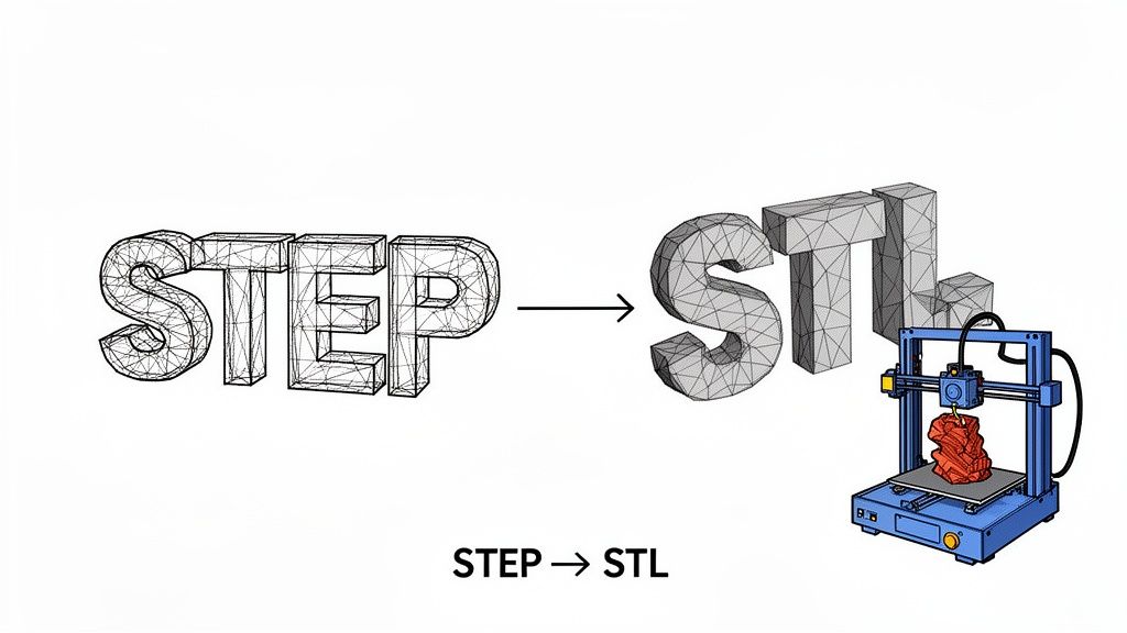
فكر في الأمر بهذه الطريقة: يصف ملف STEP كرة مثالية باستخدام صيغة رياضية واحدة وأنيقة. لا يمكن لطابعتك ثلاثية الأبعاد العمل بذلك. تحتاج إلى مجموعة من التعليمات البسيطة والمباشرة. يوفر ملف STL تلك التعليمات من خلال تقريب سطح الكرة باستخدام مئات أو حتى آلاف من المثلثات الصغيرة المسطحة.
المحول هو المترجم الذي يحول اللغة المعقدة لتصميم الهندسة إلى اللغة العملية خطوة بخطوة لطابعة ثلاثية الأبعاد. هذه ليست مجرد عملية تبديل تنسيق؛ إنها إعادة تصور كاملة لجيومترية الكائن.
لماذا تعتبر هذه التحويلة مهمة جدًا
المخاطر عالية لأن التحويل السيء يؤدي إلى طباعة سيئة. قد يحتوي ملف STL منخفض الجودة على فجوات، مثلثات غير موضوعة بشكل صحيح، أو تشطيب كتلي يبدو مختلفًا تمامًا عن تصميمك الأصلي.
- للمهندسين: يعني سير العمل الجيد للتحويل الانتقال من تصميم في Fusion 360 أو SolidWorks إلى نموذج أولي مادي على مكتبك في غضون ساعات، وليس أيام. إنه يسرع بشكل كبير من عملية التكرار وتطوير المنتجات.
- للهواة: يفتح عالمًا من الاحتمالات، مما يتيح لك الحصول على أجزاء ميكانيكية معقدة عبر الإنترنت، وتعديلها، وطبعها دون الحاجة إلى برامج باهظة الثمن من الدرجة الاحترافية للتحويل.
لفهم لماذا هذا مهم حقًا، يساعد أن نفهم ما هو التصنيع الإضافي ككل. إنها التكنولوجيا التي تنفخ الحياة في هذه الملفات الرقمية، مما يجعل عملية التصميم إلى الكائن ممكنة.
لجعل التمييز أوضح، إليك تحليل سريع لكيفية اختلاف هذين التنسيقين في جوهرهما.
مقارنة سريعة بين STEP و STL
تسلط هذه الجدول الضوء على الاختلافات الأساسية بين العالم الدقيق والرياضي لـ STEP والعالم العملي القائم على الشبكة لـ STL.
| السمة | STEP (المعيار لتبادل بيانات نموذج المنتج) | STL (لغة التقطيع القياسية) |
|---|---|---|
| الهندسة | يحدد الكائنات باستخدام منحنيات وسطح رياضي دقيق (NURBS). إنه تمثيل دقيق. | يقرب الأسطح باستخدام شبكة من المثلثات المترابطة (التقطيع). إنه تقريب. |
| حجم الملف | عادة ما يكون أصغر وأكثر كفاءة للنماذج المعقدة والمنحنية. | يمكن أن يصبح كبيرًا جدًا، حيث تحتاج المزيد من المثلثات لتمثيل الأسطح السلسة بدقة. |
| الدقة | بدون فقدان. الهندسة مثالية رياضيًا ويمكن توسيعها بلا حدود دون فقدان التفاصيل. | مع فقدان. الدقة ثابتة بعدد المثلثات. التكبير سيظهر الأوجه المسطحة. |
| قابلية التعديل | قابل للتعديل بشكل كبير في برامج CAD. يمكنك تعديل الميزات والأبعاد والعلاقات. | صعب التعديل. تعديل الشبكة معقد وغالبًا ما يتطلب برامج متخصصة. |
| حالة الاستخدام | تصميم CAD الاحترافي، والهندسة، والتصنيع، وتبادل البيانات بين أنظمة مختلفة. | أساسي للطباعة ثلاثية الأبعاد، والنماذج الأولية السريعة، والتصنيع بمساعدة الكمبيوتر (CAM). |
فهم هذه الاختلافات يوضح لماذا التحويل ليس مجرد عملية "حفظ باسم" - إنها ترجمة حاسمة حيث تتبادل الكمال الرياضي بالعملية القابلة للطباعة.
الحاجة المتزايدة للأدوات الفعالة
مع ازدهار سوق الطباعة ثلاثية الأبعاد، أصبحت الحاجة إلى محولات موثوقة أكثر إلحاحًا من أي وقت مضى. تم تقييم السوق بـ 30.55 مليار دولار أمريكي في عام 2025 ومن المتوقع أن يصل إلى 168.93 مليار دولار أمريكي بحلول عام 2033، مما يعكس معدل نمو سنوي مركب ضخم قدره 23.9%.
هذا الانفجار في الاستخدام يعني أن المزيد من الأشخاص يواجهون هذا الاختناق في التحويل. تجعل الأداة الجيدة سير العمل سلسًا، بينما تخلق الأداة السيئة صداعًا.
ستوجهك هذه الدليل خلال الطرق المختلفة للتعامل مع هذا التحويل، من برامج سطح المكتب القوية إلى الأدوات الخفيفة التي تركز على الخصوصية والتي تعمل مباشرة في متصفحك. معرفة مزايا وعيوب كل منها ستساعدك في اختيار سير العمل المناسب، سواء كانت أولويتك القصوى هي الدقة المطلقة، أو السرعة الخام، أو الحفاظ على أمان تصميماتك.
ضبط إعدادات التحويل المثالية
الانتقال من ملف STEP إلى STL ليس مجرد عملية "حفظ باسم" بسيطة. إنها عملية ترجمة حيث تقوم بتحويل جسم مثالي محدد رياضيًا إلى شبكة من مثلثات بسيطة يمكن لطابعة ثلاثية الأبعاد فهمها فعليًا.
القرارات التي تتخذها هنا حاسمة. إنها تحدد الجودة النهائية للكائن المطبوعة. فكر في الأمر أقل كحفظ مستند وأكثر كتصوير صورة - الإعدادات التي تختارها الآن ستحدد مدى وضوح وتفاصيل الصورة النهائية. هدفك هو العثور على تلك النقطة المثالية بين سطح جميل وسلس وحجم ملف لن يجعل جهاز التقطيع الخاص بك يتعطل. عدد قليل جدًا من المثلثات، وسيبدو نموذجك كتليًا؛ عدد كبير جدًا، وستحصل على ملف ضخم يصعب التعامل معه.
إتقان دقة الشبكة
تسمى عملية تحويل منحنيات ملف STEP السلسة إلى مثلثات STL بـ التقطيع. ستمنحك أي محول جيد السيطرة على ذلك، عادةً من خلال إعدادين رئيسيين: انحراف الوتر والتحمل الزاوي.
انحراف الوتر (يسمى أحيانًا انحراف خطي) يحدد الحد الأقصى للمسافة المسموح بها بين سطح STEP الأصلي ووجه مثلث STL. قيمة أصغر تعني سطحًا أكثر دقة، ولكن على حساب المزيد من المثلثات وحجم ملف أكبر.
التحمل الزاوي (أو انحراف الزاوية) يحدد الحد الأقصى للزاوية بين المثلثات المجاورة. هذا هو الإعداد الذي تستخدمه لالتقاط التفاصيل الدقيقة على الأسطح المنحنية بإحكام. زاوية أصغر تجبر البرنامج على استخدام المزيد من المثلثات لتقريب المنحنى، مما يحافظ على تلك الأشكال الدقيقة.
بالنسبة لشيء مثل دعامة ميكانيكية وظيفية حيث تكون الدقة البعدية هي كل شيء، سترغب في إعطاء الأولوية لانحراف وتر منخفض. ولكن إذا كنت تطبع تمثالًا مصغرًا مفصلًا، فإن التحمل الزاوي الأصغر يصبح أكثر أهمية للحفاظ على المنحنيات من الظهور كأشكال مسننة.
البحث عن التوازن الصحيح
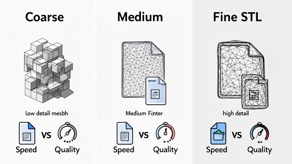
لا يوجد إعداد "أفضل" واحد هنا. تعتمد الدقة المثالية تمامًا على ما تصنعه.
- للنماذج الأولية السريعة: استخدم شبكة أكثر خشونة (قيم انحراف أعلى). إنها تتحول بشكل أسرع، الملف أصغر، وتطبع بشكل أسرع. هذا يتيح لك اختبار الشكل والملاءمة دون الانتظار لفترة طويلة حتى تنتهي الطباعة عالية التفاصيل.
- لأجزاء ذات جودة إنتاج: ستحتاج إلى شبكة أدق بكثير (قيم انحراف أقل) للحصول على تشطيب سطحي ناعم يمثل التصميم الأصلي لـ CAD بدقة، خاصة للنماذج ذات الأشكال العضوية المعقدة.
هذه المقايضة هي واحدة من التحديات الرئيسية لأي محول STEP إلى STL. على سبيل المثال، لاحظ المهندسون في DigiFabster أن تصديرات STL الافتراضية لديهم تجعل نماذج STEP التفصيلية تبدو "خام وكتلية". بعد الكثير من الاختبارات، استقروا على إعداد تجزئة 20 ميكرون القياسي. بينما زاد هذا من متوسط حجم الملف بنسبة 500%، إلا أنه أنتج رسومات ناعمة بما يكفي لتلبية احتياجاتهم في التصنيع الاحترافي. يمكنك قراءة المزيد عن رحلتهم لتحقيق توازن حجم الملف والجودة.
اختيار تنسيق الإخراج: ثنائي مقابل ASCII
بعد ضبط الشبكة، سترى غالبًا خيارًا بين تنسيقين لـ STL: ثنائي و ASCII. يبدو أن الفرق صغير، لكنه يؤثر بشكل كبير على حجم الملف وقابلية الاستخدام.
- STL ثنائي: هذا هو الخيار الذي تريده 99% من الوقت. يخزن بيانات المثلثات في كود مضغوط يمكن قراءته بواسطة الآلات. الملفات الناتجة صغيرة—غالبًا 4-5 مرات أصغر—وتتم معالجتها بشكل أسرع بكثير بواسطة أدوات القطع. بالنسبة لجميع طباعة ثلاثية الأبعاد تقريبًا، هذا هو الخيار الأفضل.
- STL ASCII: هذا التنسيق يخزن نفس البيانات في نص عادي. يمكنك فتحه حرفيًا في Notepad وقراءة الإحداثيات. بينما يكون هذا مفيدًا لأغراض تصحيح الأخطاء أو التحرير اليدوي، فإنه ينتج ملفات أكبر بشكل كبير. ما لم يكن لديك سبب محدد جدًا للقيام بذلك، تجنب هذا التنسيق.
الاستنتاج بسيط: دائمًا قم بالتصدير كـ STL ثنائي. إنه يوفر المساحة، ويحمّل أسرع، وهو المعيار الصناعي لسبب وجيه.
التحقق من الوحدات والمقياس
إعداد أخير حاسم يجب التحقق منه هو وحدة القياس. لا يوجد شيء أكثر إحباطًا من استيراد نموذجك إلى أداة القطع فقط لرؤيته يظهر كنقطة مجهرية أو كائن ضخم يملأ لوحة البناء بالكامل.
تحدث هذه المشكلة الكلاسيكية عندما تختلف البرامج المستخدمة في التصدير وأداة القطع حول ما إذا كانت وحدات النموذج بالمليمترات أو بالبوصات. الغالبية العظمى من سير عمل الطباعة ثلاثية الأبعاد تعتمد على المليمترات (مم). قبل أن تضغط على تصدير، تحقق مرة أخرى من أن برنامج CAD الخاص بك أو المحول مضبوط على الإخراج بالمليمترات.
إذا قمت بفتح STL وكان حجمه خاطئًا، فإن أول شيء يجب التحقق منه هو عامل المقياس. من المؤكد تقريبًا أنه سيكون خاطئًا بعامل 25.4—الرقم السحري لتحويل البوصات إلى مليمترات. بينما يمكنك إصلاح ذلك بسهولة في أداة القطع الخاصة بك، فإن الحصول على الأمر بشكل صحيح أثناء التحويل يوفر عليك تلك الخطوة الإضافية المزعجة.
البحث عن الأداة المناسبة لتحويل STEP إلى STL
قد تشعر وكأنك تغرق في الخيارات عندما تحتاج إلى تحويل ملف STEP إلى STL. هل تستخدم برنامج CAD قوي، أو أداة سريعة عبر الإنترنت، أم هناك شيء بينهما؟ الحقيقة هي أن أفضل محول STEP إلى STL بالنسبة لك يعتمد على ما تحاول تحقيقه.
اختيار الأداة المناسبة لا يتعلق فقط بالحصول على ملف قابل للاستخدام؛ بل يتعلق بإيجاد الطريق الأكثر ذكاءً لسير عملك. يحتاج الهواة الذين يطبعون تمثالًا رائعًا إلى متطلبات مختلفة تمامًا عن المهندسين الذين يقومون بنمذجة منتج جديد سري. دعنا نستعرض الخيارات الرئيسية لنكتشف أيها يناسبك بشكل أفضل.
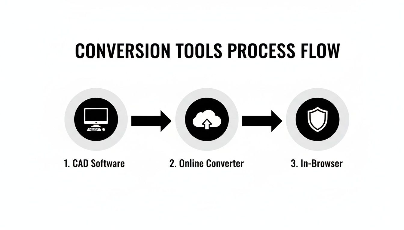
برامج CAD الاحترافية على سطح المكتب
إذا كنت مهندسًا أو مصممًا تعيش بالفعل في بيئة CAD احترافية، فإن الطريق الأكثر وضوحًا هو استخدام الأدوات التي لديك بالفعل. برامج مثل FreeCAD، Autodesk Fusion 360، وSolidWorks جميعها تحتوي على مصدّرين قويين مدمجين تتعامل بشكل رائع مع تحويلات STEP إلى STL.
الميزة الكبيرة هنا هي التحكم. تمنحك هذه البرامج وصولًا مباشرًا ودقيقًا إلى جميع إعدادات الشبكة الحرجة—انحراف الوتر، التسامح الزاوي، أيًا كان. يمكنك ضبط الإخراج بدقة جراحية، مما يضمن أن STL النهائي مناسب تمامًا لطابعتك ثلاثية الأبعاد والهندسة المحددة للجزء.
لكن كل هذه القوة تأتي بسعر: منحنى تعلم حاد ومتطلبات نظام ثقيلة. إذا لم تكن مستخدمًا لـ CAD بالفعل، فإن تنزيل وتعلم برنامج مثل FreeCAD لمجرد تحويل لمرة واحدة يشبه استخدام مطرقة ثقيلة لكسر جوزة. إنه مبالغ فيه تمامًا.
أدوات سطر الأوامر للتشغيل الآلي
بالنسبة للمطورين، والمستخدمين المحترفين، أو أي شخص يواجه جبلًا من الملفات للتحويل، فإن أدوات واجهة سطر الأوامر (CLI) هي تغيير قواعد اللعبة. هذه برامج خفيفة الوزن تقوم بتشغيلها من محطة، مما يتيح لك كتابة نصوص وأتمتة العملية بالكامل من البداية إلى النهاية.
تخيل فقط أن لديك مجلدًا يحتوي على 100 ملف STEP يحتاج جميعها إلى التحويل باستخدام نفس إعدادات الدقة العالية. القيام بذلك يدويًا سيكون مملًا للغاية. باستخدام أداة CLI، يمكن لنص بسيط أن يتعامل مع المجلد بالكامل، ويطبق قواعد التحويل الخاصة بك، ويخرج STLs مثالية بينما تتناول فنجان قهوة. بالنسبة للتصنيع وسير العمل الاحترافي، هذه وسيلة رائعة لتوفير الوقت.
بالطبع، تفترض هذه الطريقة أنك مرتاح للعمل في بيئة سطر الأوامر. إنها بعيدة عن كونها حلاً يعتمد على النقرة، ولكن بالنسبة لأي شخص يحتاج إلى معالجة الملفات على نطاق واسع، فإن الكفاءة لا تضاهى.
راحة ومخاطر المحولات عبر الإنترنت
ستغمر شاشة جهازك نتائج بحث سريعة عن "محول STEP إلى STL" مع مواقع تعد بتحويلات فورية ومجانية. سير العمل مغري ببساطته: قم بتحميل STEP، اضغط على زر، ثم قم بتنزيل STL. بالنسبة للنماذج البسيطة التي ليست حساسة، لا يمكنك التغلب على الراحة.
لكن تلك الراحة تأتي بتكلفة خفية ضخمة: الخصوصية.
في كل مرة تقوم فيها بتحميل تصميم إلى خادم طرف ثالث، تفقد السيطرة على ملكيتك الفكرية. بالنسبة لمشروع شخصي أو نموذج مفتوح المصدر، قد يكون ذلك خطرًا أنت مستعد لتحمله. ولكن بالنسبة لتصميم ملكية، أو عمل للعميل، أو نموذج حساس؟ إنه كسر للصفقة.
بعيدًا عن كابوس الأمان، تقدم المحولات عبر الإنترنت عادةً كمية ضئيلة من التحكم. قد تحصل على بعض الإعدادات المسبقة مثل "منخفض، متوسط، عالي"، لكنك تفقد القدرة على ضبط الشبكة بدقة. غالبًا ما تُترك مع STL إما كبير جدًا وذو دقة منخفضة أو ضخم بشكل غير مبرر.
أدوات داخل المتصفح: الأفضل من كلا العالمين
تظهر فئة جديدة وأكثر ذكاءً من الأدوات: المحولات المحلية داخل المتصفح. تعمل هذه على مبدأ مختلف تمامًا. بدلاً من تحميل ملفك إلى خادم في مكان غير معروف، تحدث كل سحر التحويل داخل متصفح الويب الخاص بك، على جهازك الخاص. بياناتك لا تغادر جهاز الكمبيوتر الخاص بك أبدًا.
تمنحك هذه الطريقة بساطة النقرة والذهاب لأداة الويب مع الأمان القوي لتطبيق سطح المكتب. تحصل على واجهة نظيفة وودية دون تثبيت أي قطعة من البرمجيات، كل ذلك مع الحفاظ على تصميماتك خاصة تمامًا.
تم بناء أدوات مثل ShiftShift Extensions حول هذا النموذج الذي يركز على الخصوصية. يتيح لك عارض النماذج ثلاثية الأبعاد المدمج والمحولات سحب وإفلات ملف STEP، وفحصه من كل زاوية، وتحويله إلى STL دون أن تلمس أي بايت من نموذجك الإنترنت. هذه هي الحل المثالي لأي شخص يحتاج إلى تحويل سريع وآمن دون عبء CAD الاحترافي أو مخاطر الخدمة عبر الإنترنت.
كيفية اختيار الطريق الصحيح
لمساعدتك في اتخاذ القرار، قمت بتجميع مقارنة سريعة. فقط فكر في ما هو الأكثر أهمية لمشروعك، وستصبح الأداة المناسبة واضحة بسرعة.
مقارنة طرق تحويل STEP إلى STL
| طريقة التحويل | الأفضل لـ | الميزة الرئيسية | العيب الرئيسي |
|---|---|---|---|
| CAD الاحترافي | المهندسون والمصممون والمستخدمون الذين يحتاجون إلى أقصى درجات الدقة. | تحكم كامل في كل إعدادات التحويل للحصول على جودة مثالية. | منحنى تعلم مرتفع، يتطلب أجهزة قوية، وغالبًا ما يكون مكلفًا. |
| أدوات سطر الأوامر | المطورون والمستخدمون الذين يحتاجون إلى معالجة العديد من الملفات في وقت واحد. | لا يمكن منافسته في معالجة الدفعات، والأتمتة، ودمج السكربتات. | يتطلب معرفة تقنية وليس سهل الاستخدام للملفات الفردية. |
| محولات الإنترنت | تحويلات سريعة وغير حساسة لمشاريع الهواة. | سهل الاستخدام للغاية ويمكن الوصول إليه من أي جهاز يحتوي على متصفح. | مخاطر كبيرة على الخصوصية والأمان؛ تحكم محدود جدًا في الإعدادات. |
| أدوات المتصفح | المستخدمون الذين يفضلون الخصوصية والسرعة وسهولة الاستخدام. | معالجة آمنة ومحلية بدون تحميل بيانات؛ بسيطة وسريعة. | قد لا تقدم التحكم المتقدم والدقيق لبرامج CAD الكاملة. |
في نهاية اليوم، عالم أدوات محول step stl لديه خيار للجميع. من خلال فهم الموازنة بين التحكم والراحة والخصوصية، يمكنك اختيار الطريقة التي تناسب مشروعك واحتياجاته الأمنية بثقة.
كيفية التحقق من صحة ملف STL وحل المشكلات
لقد قمت بتحويل ملف STEP الخاص بك. رائع! لكن لا تبدأ في تشغيل الطابعة ثلاثية الأبعاد بعد. تحويل الملف شيء؛ التأكد من أنه قابل للطباعة هو شيء آخر. هذه الفحص السريع للجودة هو خط الدفاع الأخير ضد طباعة فاشلة، مما يوفر لك ساعات من الإحباط ولفة من الخيوط المهدرة.
فكر في ملف STL كتمثال رقمي مصنوع من مثلثات صغيرة، جميعها متصلة معًا. إذا كانت بعض هذه المثلثات مفقودة، أو تواجه الاتجاه الخاطئ، أو مشوشة ببساطة، فلن تعرف طابعتك ماذا تفعل. دعنا نستعرض كيفية اكتشاف هذه المشكلات قبل أن تفسد يومك.
يمكن أن يؤثر المسار الذي تسلكه لتحويل ملفك—سواء كان من خلال برنامج CAD كامل أو أداة سريعة عبر الإنترنت—على أنواع الأخطاء التي قد تراها. كل طريقة لها خصائصها الخاصة.
لهذا السبب، فإن إجراء فحص سريع بعد التحويل هو دائمًا فكرة جيدة، بغض النظر عن الأداة التي استخدمتها.
التحقق من نموذج محكم
القاعدة رقم واحد المطلقة لملف STL القابل للطباعة هي أنه يجب أن يكون محكمًا—يُطلق عليه أيضًا "متعدد الأوجه". تخيل أن نموذجك هو دلو. إذا كان به أي ثقوب، فلن يتمكن من الاحتفاظ بالماء. تفكر أداة التقطيع ثلاثية الأبعاد بنفس الطريقة؛ تحتاج إلى كائن محكم تمامًا لفهم مكان "الداخل" و"الخارج".
العديد من أدوات التقطيع الحديثة مثل PrusaSlicer أو Ultimaker Cura ذكية بما يكفي لاكتشاف وإصلاح هذه الثقوب تلقائيًا في بعض الأحيان. ولكن للحصول على عمل أكثر شمولاً، فإن أداة مثل Autodesk Meshmixer لا تقدر بثمن. ستحدد بصريًا أي فجوات وتمنحك الأدوات لإصلاحها بشكل صحيح.
تصحيح الاتجاهات السطحية
كل مثلث في شبكة STL الخاصة بك له اتجاه—يواجه إما "الداخل" أو "الخارج". هذا الاتجاه هو الاتجاه السطحي له. إذا تم قلب بعض الاتجاهات أثناء التحويل وأشارت إلى الداخل، فإن أداة التقطيع ستحتار وتعامل ذلك الجزء من النموذج كمساحة فارغة، مما يؤدي إلى فجوات غريبة أو أقسام مفقودة في طباعةك.
نموذج ذو اتجاهات مقلوبة هو أحد أكثر المشاكل شيوعًا—والتي تسبب الارتباك—التي ستواجهها. قد يبدو جيدًا تمامًا في عارض بسيط، لكنه سيتحول إلى فوضى مشوشة عند التقطيع. دائمًا استخدم عارضًا يمكنه تصور الاتجاهات إذا كنت تشك في وجود مشكلة.
لحسن الحظ، فإن الإصلاح عادة ما يكون بسيطًا. معظم برامج 3D، بما في ذلك Meshmixer وحتى Blender، تحتوي على وظيفة مثل "إعادة حساب الاتجاهات" أو "قلب الاتجاهات" التي يمكن أن توحد كل شيء بنقرة واحدة.
إصلاح الحواف غير المتعددة الأوجه
هذه واحدة أكثر تعقيدًا. يحدث الهندسة غير المتعددة الأوجه عندما يحتوي نموذجك على حواف لا يمكن أن توجد في العالم الحقيقي. مثال كلاسيكي هو عندما تشترك حافة في أكثر من مثلثين، مما يخلق تقاطعًا حيث لا تستطيع أداة التقطيع تحديد ما هو داخل أو خارج.
تشمل الأخطاء غير المتعددة الأوجه الأخرى الوجوه الداخلية المحاصرة داخل النموذج أو الحواف التي تطفو، مرتبطة بلا شيء. هذه الغموضات هي وصفة لكارثة في أداة التقطيع. ستساعدك أداة إصلاح الشبكة الجيدة في العثور على هذه النقاط المشكلة، مما يتيح لك حذف الهندسة السيئة أو فصل الأجزاء بشكل صحيح إلى قشور متميزة خاصة بها.
سيناريوهات شائعة لحل المشكلات
بجانب الأخطاء المعقدة في الشبكة، يمكن أن تظهر بعض المشاكل الشائعة الأخرى. إليك بعض المشتبه بهم المعتادين وكيفية التعامل معهم:
المشكلة: يبدو نموذجى كتلة أو ذو زوايا.
- الحل: كانت دقة التصدير لديك منخفضة جدًا. عد إلى محولك وقم بتصدير الملف مرة أخرى، ولكن هذه المرة استخدم انحرافًا وترًا أقل. سيؤدي ذلك إلى إنشاء شبكة أكثر دقة وتفصيلاً.
المشكلة: الملف إما ميكروسكوبي أو ضخم عند استيراده.
- الحل: هذه غالبًا ما تكون مشكلة في وحدات القياس. من المحتمل أنك قمت بالتصدير بالبوصات بينما كانت أداة التقطيع تتوقع المليمترات. يمكنك إما إعادة التصدير باستخدام الوحدات الصحيحة (المليمترات هي المعيار للطباعة ثلاثية الأبعاد) أو ببساطة تغيير حجم النموذج في أداة التقطيع الخاصة بك بعامل 25.4 للتحويل من البوصات إلى المليمترات.
المشكلة: تستغرق أداة التقطيع وقتًا طويلاً لمعالجة الملف.
- الحل: الشبكة كثيفة جدًا! كانت إعدادات التحويل لديك مرتفعة جدًا، مما أدى إلى إنشاء ملف ضخم يحتوي على ملايين المثلثات التي لا تحتاجها فعليًا. أعد التصدير بقيم انحراف أعلى قليلاً لتقليل عدد المضلعات. إذا كنت تعمل مع العديد من الملفات، يمكن أن تساعدك أداة عرض النماذج ثلاثية الأبعاد الخفيفة في فحصها بسرعة قبل أن ترسلها إلى أداة التقطيع.
أتمتة التحويلات مع سير العمل المتقدم
بالنسبة لأي شخص يعمل في الهندسة أو تصميم المنتجات، فإن تحويل الملفات واحدًا تلو الآخر هو مضيعة كبيرة للوقت. هذه الحلقة اليدوية—فتح ملف STEP، تعديل الإعدادات، تصدير إلى STL، حفظ، تكرار—مناسبة لنموذج أولي واحد. ولكن عندما تكون أمام تجميع يحتوي على العشرات، أو حتى المئات، من المكونات؟ تصبح عنق زجاجة خطير في الإنتاج. هنا يجب عليك توسيع سير العمل الخاص بك. الأمر لا يتعلق فقط بالراحة؛ إنه ضرورة.
تؤدي أتمتة عملية تحويل STEP إلى STL إلى إخراجك من العمل المتكرر، وتضمن تحويل كل نموذج بنفس الإعدادات، وتحررك لتحديات التصميم التي تهم حقًا. من خلال الاعتماد على السكربتات وواجهات سطر الأوامر، يمكنك تحويل هذه المهمة المملة إلى عملية خالية تمامًا من الجهد.
الاستفادة من سطر الأوامر لمعالجة الدفعات
بدلاً من النقر عبر واجهة رسومية لكل ملف على حدة، تستخدم سير العمل الآلي القوة الخام لأدوات سطر الأوامر. هذه برامج خفيفة الوزن تقوم بتشغيل التحويلات بناءً على أوامر نصية بسيطة، مما يجعلها مثالية للبرمجة النصية. يمكنك كتابة نص برمجي صغير يشير إلى مجلد مليء بملفات STEP ويخبر المحول بمعالجة جميعها دفعة واحدة.
لنقل أنك بحاجة إلى تجهيز تجميع منتج كامل للطباعة ثلاثية الأبعاد. يمكن لنص برمجي بسيط أن يتولى كل هذا من أجلك:
- التنقل عبر كل ملف
.stepأو.stpفي مجلد مشروعك. - تطبيق مجموعة محددة مسبقًا من إعدادات الشبكة عالية الدقة للأجزاء النهائية للإنتاج.
- ربما حتى توليد مجموعة ثانية منخفضة الدقة لطباعة نماذج سريعة، ذات جودة مسودة.
- تنظيم جميع ملفات STL المنتهية بشكل مرتب في دليل "الإخراج"، مع إمكانية إعادة تسميتها بناءً على تقليد محدد.
تضمن هذه الطريقة تحويل كل نموذج بإعدادات متطابقة وخالية من الأخطاء. هذه مستوى من الاتساق يكاد يكون من المستحيل الحفاظ عليه عندما تقوم بكل شيء يدويًا. للحصول على نظرة أعمق حول أتمتة العمليات التجارية مثل هذه، تحقق من الدليل الكامل لبرامج أتمتة سير العمل؛ حيث يقدم بعض الرؤى الرائعة حول الأدوات المتاحة.
مثال عملي باستخدام بايثون
بايثون خيار رائع لهذا النوع من الأتمتة، بفضل المكتبات التي يمكن أن تتفاعل مباشرة مع نوى CAD. على سبيل المثال، باستخدام مكتبة مبنية على محرك هندسي قوي مثل OpenCASCADE، يمكنك كتابة نص برمجي يدير عملية التحويل بالكامل دون الحاجة لفتح برنامج CAD.
إليك فكرة مفاهيمية عن شكل نص برمجي بسيط بلغة بايثون:
نص برمجي مفاهيمي لتحويل دفعي
import os from some_cad_library import STEPReader, STLWriter
حدد مكان ملفاتك وأين يجب أن تذهب
input_folder = "/path/to/your/step_files/" output_folder = "/path/to/your/stl_files/"
حدد جودة الشبكة المطلوبة مرة واحدة
mesh_deflection = 0.01 # إعداد دقيق للتفاصيل العالية
التكرار عبر جميع الملفات في مجلد الإدخال
for filename in os.listdir(input_folder): if filename.endswith(".step") or filename.endswith(".stp"): step_path = os.path.join(input_folder, filename)
    # قراءة نموذج STEP
    model = STEPReader.read(step_path)

    # إنشاء الشبكة باستخدام إعدادك
    model.tessellate(mesh_deflection)

    # تحديد اسم ملف الإخراج الجديد
    stl_filename = filename.replace(".step", ".stl").replace(".stp", ".stl")
    stl_path = os.path.join(output_folder, stl_filename)

    # كتابة ملف STL النهائي
    STLWriter.write(model, stl_path)
    print(f"تم تحويل {filename} إلى STL بنجاح.")
نص برمجي بسيط مثل هذا يقوم بأتمتة سير عمل كان سيستغرق ساعات من النقر. مبادئ الأتمتة تنطبق على جميع أنواع تحديات البيانات، كما يمكنك أن ترى مع شيء مثل محول CSV إلى Excel، حيث توفر النصوص لك من العمل اليدوي الممل.
الاندماج في خطوط تطوير حديثة
السحر الحقيقي يحدث عندما تقوم بتوصيل هذه النصوص في أنظمة تطوير أكبر، مثل خط أنابيب التكامل المستمر/النشر المستمر (CI/CD). هذه الفكرة، المستعارة من عالم البرمجيات، تعمل بشكل رائع أيضًا لتصميم الأجهزة.
تخيل هذا: في كل مرة يقوم فيها مصمم بإجراء تغيير على ملف STEP في نظام التحكم في الإصدارات مثل Git، يتم تشغيل نص التحويل الخاص بك تلقائيًا. يقوم هذا النص على الفور بإنشاء STL جديدة، والتي يمكن بعد ذلك إدخالها في أداة تحليل آلي، أو التحقق منها بواسطة مقطع، أو حتى إرسالها مباشرة إلى طابعة ثلاثية الأبعاد لنموذج أولي جديد.
تخلق هذه الإعدادات سير عمل سلس "دفع للطباعة". إنها تغلق الفجوة بين تغيير التصميم ووجود جزء مادي في يديك، مما يسمح لفرق الأجهزة بالتكرار بالسرعة والمرونة التي تمتلكها فرق البرمجيات منذ سنوات. من خلال احتضان الأتمتة، يتحول محول STEP إلى STL من أداة بسيطة إلى جزء حيوي من نظام هندسي حديث وفعال.
إلى أين تتجه التحويلات: في المتصفح، خاصة، ومتكاملة
أي شخص كان في هذا المجال لفترة من الوقت قد لاحظ اتجاهًا واضحًا: نحن نبتعد عن البرمجيات المكتبية الثقيلة التي تتطلب تثبيتات معقدة. مستقبل تحويل نماذج 3D يحدث مباشرة في متصفحك، مما يلغي متاعب التنزيلات والتحديثات. هذا ليس مجرد مسألة راحة؛ إنه تحول ضخم نحو السرعة، والوصول، والأهم من ذلك، الخصوصية.
أصبح التفكير في الخصوصية كأولوية ليس مجرد "ميزة إضافية". إنه المعيار الجديد. يحتاج المهندسون والمصممون باستمرار إلى عرض والتحقق من وتحويل النماذج، لكن رفع الملكية الفكرية الحساسة إلى خادم سحابي عشوائي ليس خيارًا. هنا تأتي أدوات المتصفح التي تعمل محليًا على جهازك لتغيير اللعبة. تحصل على أمان قوي لبرامج سطح المكتب مع سهولة الوصول البسيطة لتطبيق ويب.
أصبحت سير العمل الآمنة هي القاعدة
تدفع هذه الحركة بالكامل من خلال الانفجار في الطباعة ثلاثية الأبعاد، خاصةً للنماذج الأولية السريعة. نحن ننظر إلى سوق من المتوقع أن يقفز من 19.8 مليار دولار أمريكي في 2023 إلى 135.4 مليار دولار أمريكي بحلول 2033. هذا النوع من النمو يخلق طلبًا هائلًا على أدوات تحويل أفضل وأسرع. لمزيد من المعلومات حول هذا، تحقق من البيانات حول مسار سوق الطباعة ثلاثية الأبعاد.
تم تصميم أدوات مثل ShiftShift Extensions لهذا الواقع. إنها توفر لك عارض ثلاثي الأبعاد محلي ومحول step stl يقوم بكل العمل هناك في متصفحك. هذا يعني أنه يمكنك التكرار على تصميم على الفور دون الحاجة إلى إرسال ملفك عبر الإنترنت.
الاستنتاج الكبير بسيط: يجب أن تحمي سير العمل الخاصة بك ملكيتك الفكرية بشكل افتراضي. اختيار الأدوات التي تعمل محليًا ليس مجرد ميزة - إنها ممارسة أمان حاسمة للتصميم والهندسة الحديثة.
في النهاية، أفضل الأدوات هي تلك التي تتناسب بسلاسة مع كيفية عملك بالفعل. أدوات مدفوعة بقائمة الأوامر هي مثال مثالي، حيث تضع محول step stl الآمن على بعد اختصار لوحة المفاتيح فقط. لا تجعل هذه الطريقة إنتاجيتك أعلى فحسب، بل تحافظ أيضًا على أمان بياناتك وتفتح إمكانيات قوية للجميع، من المهندسين ذوي الخبرة إلى صانعي عطلة نهاية الأسبوع. هذه المبدأ للأدوات الآمنة المستندة إلى المتصفح لا يقتصر على نماذج 3D - يمكنك رؤية اتجاه مشابه في دليلنا حول أفضل برامج تحويل PDF المجانية.
أسئلة شائعة وإجابات سريعة
عندما تبدأ في تحويل ملفات STEP، يبدو أن بعض الأسئلة تظهر دائمًا. يمكن أن يساعدك ترتيب هذه الأمور مبكرًا في تجنب الكثير من الصداع ومنع فشل الطباعة لاحقًا.
هل يمكنني تحويل ملف STL مرة أخرى إلى ملف STEP؟
الإجابة القصيرة؟ ليس حقًا، على الأقل ليس بسهولة أو نظافة. بينما تدعي بعض برامج الهندسة العكسية المتقدمة أنها تفعل ذلك، فإن تحويل STL مرة أخرى إلى STEP هو عملية فوضوية ومعقدة نادرًا ما تعطيك نتيجة مثالية.
ملف STL هو مجرد شبكة من المثلثات - إنه نموذج سطحي بدون "ذكاء" حقيقي. لا يحتوي على تاريخ تصميم غني ودقيق كما يفعل ملف STEP. محاولة إعادة بناء تلك البيانات البارامترية من شبكة بسيطة تشبه محاولة إعادة بناء المخطط الأصلي لمهندس معماري من صورة ممسوحة للمبنى المكتمل. ستحصل على شيء، لكن من المحتمل أن يكون معيبًا وسيتطلب الكثير من التنظيف اليدوي.
لماذا ملف STL المحول الخاص بي كبير جدًا؟
هذه جزء كلاسيكي - وطبيعي تمامًا - من عملية التحويل. ملف STEP هو معجزة من الكفاءة؛ فهو يصف هندسة معقدة ومنحنية باستخدام صيغ رياضية بحتة. من ناحية أخرى، يجب على ملف STL تقريب تلك المنحنيات المثالية من خلال تجميع آلاف (أو حتى ملايين) من المثلثات المسطحة الصغيرة.
كلما كنت ترغب في أن يبدو نموذجك النهائي أكثر سلاسة، كلما زادت دقة الإعدادات. هذا يجبر المحول على توليد عدد هائل من المثلثات لخلق وهم المنحنى المثالي، مما يجعل حجم الملف يتضخم بشكل طبيعي.
نصيحة احترافية: دائماً، دائماً قم بتصدير STL الخاص بك بصيغة ثنائية، وليس ASCII. إن STL ثنائي الحجم أصغر بشكل كبير—نتحدث عن أربعة إلى خمسة أضعاف أصغر—وسيكون بإمكان جهاز التقطيع ثلاثي الأبعاد الخاص بك معالجته بشكل أسرع بكثير. إنه المعيار لسبب ما.
هل تحويل من STEP إلى STL يقلل من الجودة؟
نعم، تقنياً، يتم فقدان بعض الدقة دائماً في الترجمة، لكن المفتاح هو أن أنت تتحكم في مقدار ذلك. عملية تحويل نموذج رياضي سلس إلى شبكة مثلثات تُسمى التجزئة، وهي في الأساس تقريب.
فكر في الأمر كما لو كنت تحاول رسم دائرة مثالية باستخدام سلسلة من الخطوط المستقيمة الصغيرة فقط. يمكنك التحكم في مدى قصر تلك الخطوط. من خلال تعديل إعدادات مثل انحراف الوتر والتسامح الزاوي في المحول الخاص بك، يمكنك جعل "الخطوط" (حواف المثلثات) صغيرة جداً لدرجة أن فقدان الجودة يصبح غير مرئي تماماً في الطباعة ثلاثية الأبعاد النهائية. الأمر كله يتعلق بالعثور على تلك النقطة المثالية بين نموذج جميل وسلس وحجم ملف لا يجعل جهاز الكمبيوتر الخاص بك يتعثر.
افتح عالماً من الإنتاجية مع ShiftShift Extensions، مجموعة الأدوات الشاملة للمطورين والمصممين والمستخدمين المحترفين. احصل على وصول فوري إلى العشرات من الأدوات مثل عارض النماذج ثلاثية الأبعاد الآمن، محولات الملفات، وأدوات المطورين—كل ذلك من لوحة أوامر واحدة، مباشرة في متصفحك. ابدأ مجاناً على https://shiftshift.app.